While there are some excellent commercial and residential CO2 sensors on the market, many are quite costly. In part this is due to the chip shortage, but we're also feeling the effects of the demand curve as more people learn that CO2 sensors are a reasonable proxy for COVID risk in a given space.
(FYI: there's a Bonus Guide at the bottom with instructions for using a Pimoroni Badger 2040 instead. Much simpler, but lower availability of parts. Do what you will with that information.)
In this article I'll help you figure out how to put together your own CO2 sensor out of readily available, off the shelf parts. Here are essentials and nice-to-haves which I'll go over how to get in more detail afterwards. Be aware with all these items that my selections have been made due to compatibility with Circuit Python. If you want to use a different language/framework, you may need different parts:
Essentials
- A soldering iron and solder
If you don't already have a soldering iron and don't plan on getting into electronics, I'd suggest borrowing one and the necessary solder from a pal. If it's your first soldering iron, something inexpensive with a temperature control would be good. - A microcontroller board
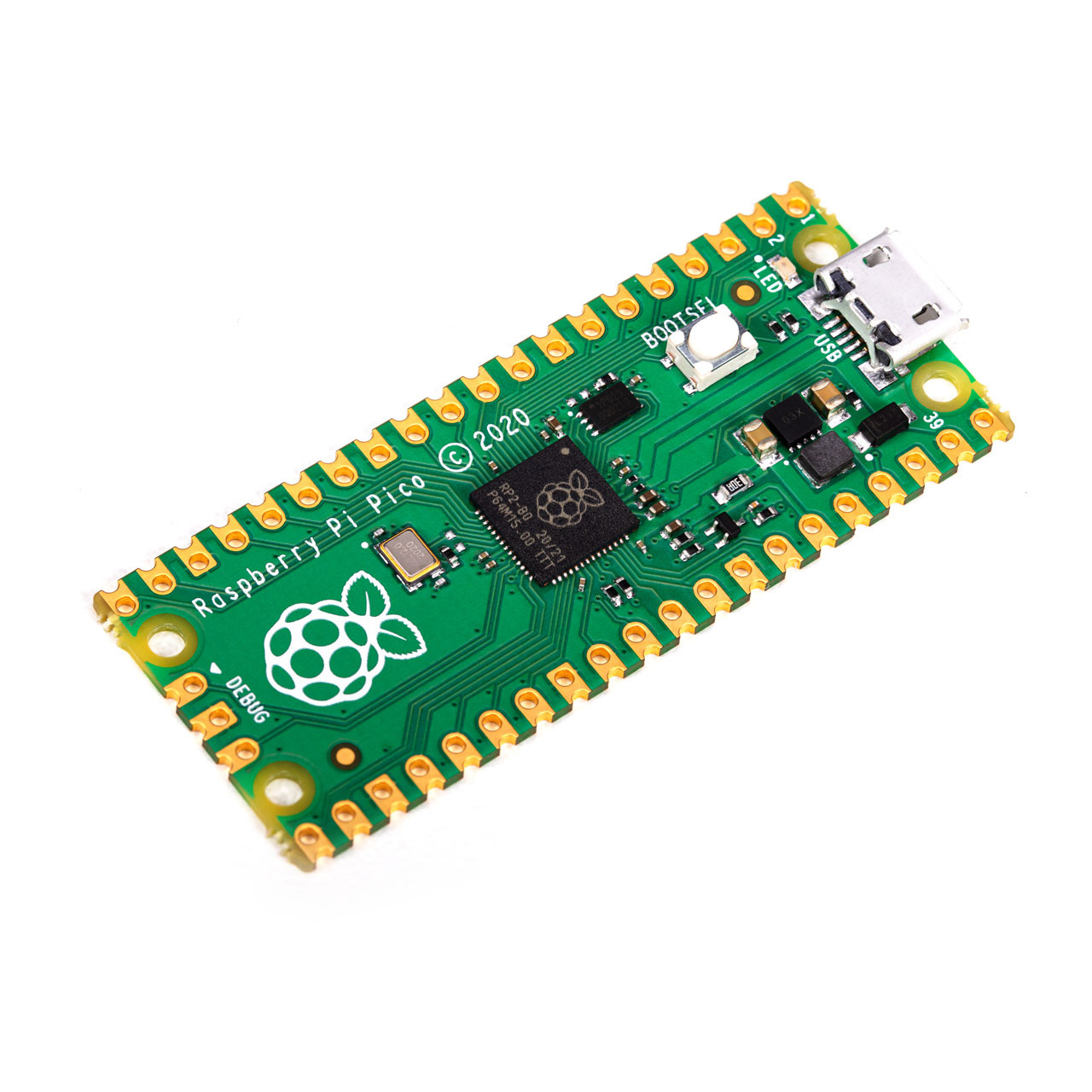
I will be using the cheap and readily-available Raspberry Pi Pico, from PiShop, Mouser, DigiKey, Adafruit, and many others. Pricing should be no more than about $7 CAD. You could also go with a board that has a built-in screen. If you can find one, you might also go with a Raspberry Pi 2040 or other board that has a built-in display such as the Badger 2040. If you go with the Badger 2040, see the BONUS GUIDE in the last section of this article.
- A quality CO2 sensor
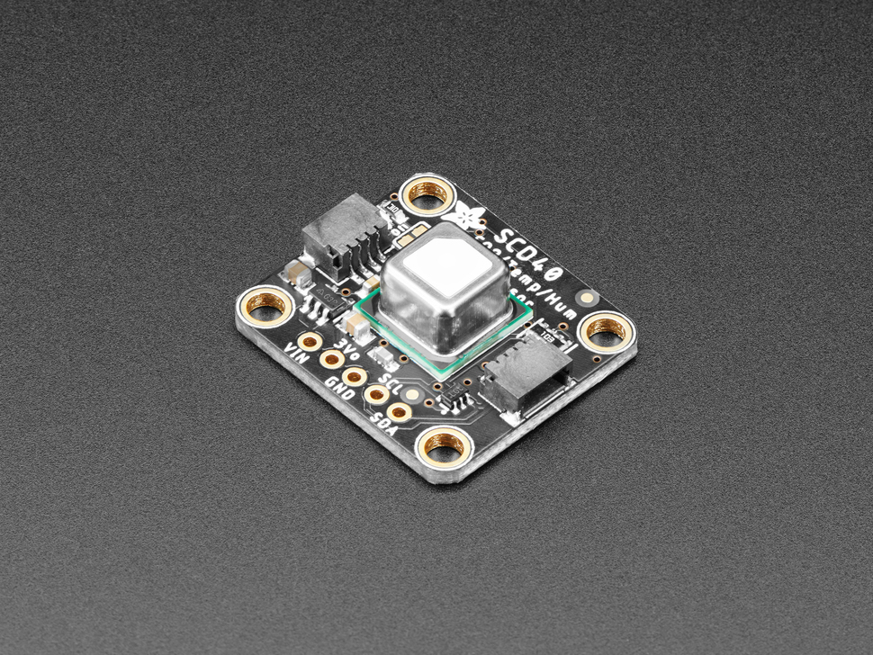
This will be the most expensive part, ranging from $40 to $100 depending on the source and quality. I'll be using the Sensirion SCD41. I happen to have it on hand but the Sensirion SCD40 is also available for a bit cheaper and the two are compatible. The chip itself is surface-mount (really hard to solder by hand) so make sure you get a breakout board with the chip pre-mounted. The best value right now seems to be the MIKROE HVAC Click board which features the SCD41 and other chips bundled at the low price of $62.10 CAD on Mouser, though I haven't worked with this board myself. If you don't mind ordering from a US site, my recommendation goes to the SCD40 breakout from Adafruit at $49.50 USD or similarly priced breakout from Sparkfun.
- A display
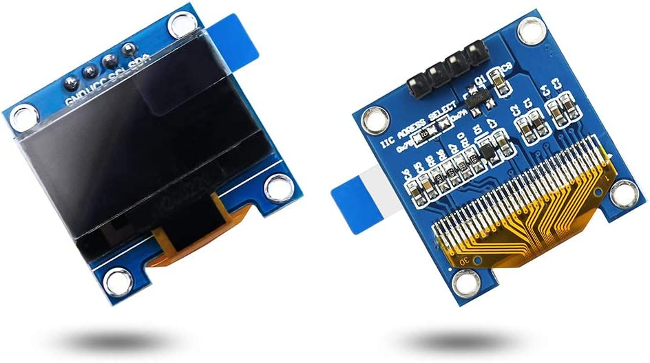
For portability, you'll need your device to have a screen. For power consumption, I'd recommend e-ink for low power but there are much cheaper options available. I happen to have an I2C 128x64 bicolor OLED I purchased from Amazon some time ago but there are many inexpensive display options you could go with. With the display, there are some things to bear in mind:
- if you want the least soldering (but slower refresh) consider an I2C display - it'll use the same pins and number of wires as the CO2 sensor. If you want a faster display consider an SPI display. My recommendation for this very basic application is I2C.
- you need to choose a display with a chipset supported in Circuit Python if you want to use my code. Specifically, I'll be using the SSD1306 library.
The (super cheap) display I'm using is still readily available on Amazon in a 3-pack at $21.99.
- Assorted wires & cables
- A USB micro cable for connecting up your computer to the microcontroller.
- You'll need some fine wires either on a spool or repurposed from other electronic devices/projects. Old ribbon cables or dissected phone/ethernet cables would be a reasonable gauge for this size work but you could go a bit larger gauge if it's all you have - internal power supply cables for PCs can also work but are at the upper end of size from what you'd want.
Nice-to-Haves
While the above are all essentials, there are some items that will make your life easier. I don't necessarily recommend you go out and get these things, especially if you're not planning on diving into electronics projects beyond this, but if you have them or don't mind spending the money, they can make things nicer:
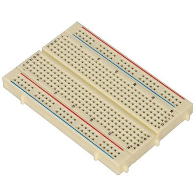
- A solderless breadboard for testing.
These you can generally get bundled into your purchases of the other items above for not too much coin. Of course you'll also need the specialized leads to connect things on them but those are also inexpensive. You benefit from the use of a solderless breadboard by being able to ensure your circuits work before making them more permanent with solder.
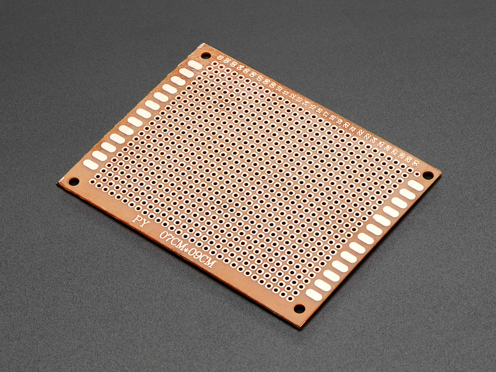
- Perfboard (AKA: protoboard) for prototyping
These are boards with rows of metal-rimmed holes drilled at regular intervals, allowing you to mount electronics to the board with solder and wire it up above or below. Of all the nonessentials I'd say this above all will make your work look a little less janky and will be easier to work with than loose wires.
"Enough with the inventory already, Aria, get to the instructions!" Okay okay, I'm getting there...
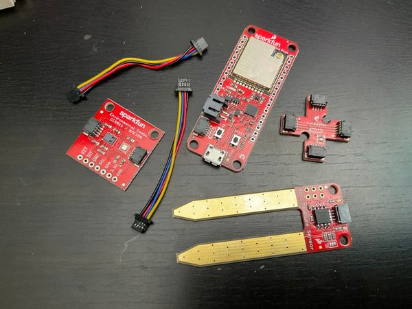
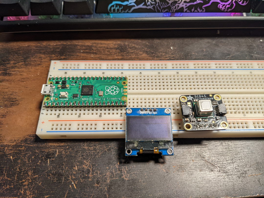
Once you have all your parts, lay out the big components in front of you so you can figure out how best to fit things together. If you are aiming to make things as compact as possible you'll have to evaluate that after you know what connections need to be made. Here's where I believe having a solderless breadboard will make your life much easier. Here's my pieces laid out in the middle sections of the breadboard (my sensor is mounted on a spacer so I know it looks like it's plugged in wrong, but the pins are actually plugged in just below the middle of the breadboard).
A note about breadboards
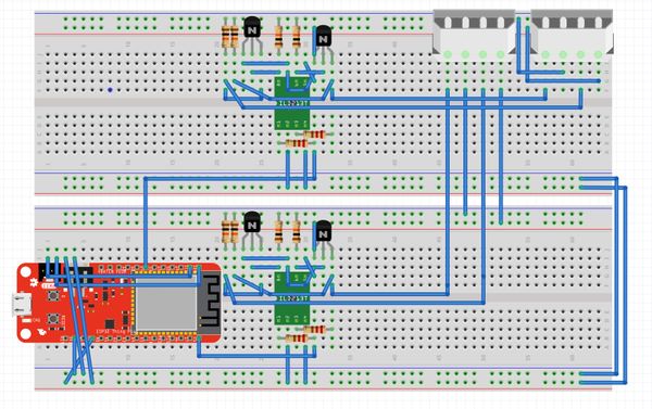
The essential thing to know about breadboards is how the holes are connected. The outer two rows (running left-to-right) on the top and bottom are "power rails" (red on my board) or "ground rails" (blue on my board) and all the holes are connected horizontally. The middle two sections (separated by a horizontal groove/gap in the centre of the board) are fully separated from each other, but within each section, the columns are connected. For instance, on my board, below, each column of 5 holes is connected vertically but is not connected horizontally, and there is no connection across the centre gap.
What this allows, if my wording hasn't been too confusing, is for boards to be placed with their pins aligned horizontally on either side of the gap so that no pin is connected to each other (until you manually connect wires between columns). All the devices in the photo below are placed such that their pins are not connected to each other, but so that there are holes available in each column for us to link the boards up with wires.
If you're using a breadboard, you need pin headers for your Pico. They don't generally come with.
Set up your Raspberry Pi Pico
Before we get to wiring, I want to make sure my Raspberry Pi Pico board (which is not brand new) is not going to run any weird programs with these new devices - I'll need to install CircuitPython and set things to a clean state. First, go to the CircuitPython website and download the latest stable .uf2 for the Pico (7.3.3 at the time of this article). You'll also need to download the applicable version (7.x currently) library bundle and extract it somewhere accessible. We'll need it once we start programming.
Get ready to plug your Pi Pico into your computer with the USB micro cable, but before actually plugging it in, put your finger on the "BOOTSEL" button on the Pico and hold it down until a few seconds after you plug the board in. Regardless of what applications are installed to the Pico, this will allow it to boot up in "bootloader" mode. Go to your computer (I'll try to be non-specific about operating systems as it should work regardless of what kind of computer you have) and look in the place where your USB drives usually show up for a drive called "RPI-RP2". If you held the BOOTSEL button correctly, the drive should appear.
Drag, copy/paste, or move the CircuitPython .uf2 file from your Downloads to the RPI-RP2 drive. Once done, the drive should disappear from your system and when the Pico reboots, you should be looking at a CIRCUITPY drive instead (if not, try unplugging and replugging in the Pico). It may have a handful of files and directories in it already. The main file we will concern ourselves with is code.py.
For now, please open code.py in a text editor (I recommend Visual Studio Code), delete all lines in the file, and save. Likewise, go to the lib directory within the CIRCUITPY drive and delete all files in that directory, if any, but leave the directory itself in place. "Eject" the CIRCUITPY drive and unplug the Pico - our Picos are now in a clean state and we'll come back to them after wiring.
The Wiring
As the pins are not labeled on the Pico, I'll reference this pinout diagram from Adafruit. Get ready for some very easy wiring. If you're wiring directly from the start or using perfboard, try to follow the ideas behind the connections I'm making, but be more direct. For instance where I use a power rail, you can safely connect all the devices up to each other directly. Same with the ground rail. Just make sure to keep your power and ground separated.
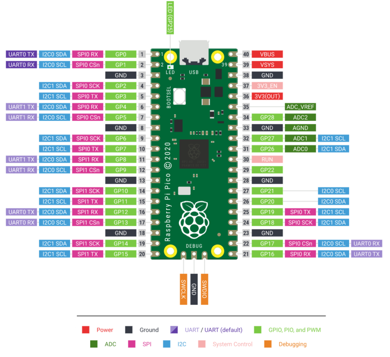
- Since the Pico will be the power source for the sensor and display, connect a wire from one of the holes above pin 36 (3.3 volt output) to the very top (horizontal) row on the breadboard. I like to use red wire for the power connections.
- Connect the VCC (power input) connection on the display to the same row you just connected the Pico's pin 36 to. Remember your connection to VCC has to be in a hole on the same side of the groove/gap as the display.
- Same deal with the sensor - connect from VIN to the top "rail" on the breadboard.
- Next, use another of the horizontal rails for ground. I like to use the one at the very bottom just to keep things separate. Connect pin 3 on the Pico to the ground rail. I'll use blue wires for these connections.
- Next, connect pin 1 (GP0) on the Pico to SDA on the display. This will be a direct connection column-to-column and I'll use a yellow wire for clarity. [SDA is the Data connection for the I2C bus]
- Connect a yellow wire from SDA on the display to SDA on the sensor - we could go directly from pin 1 (GP0) on the Pico to the sensor instead, but I'm picking the shorter path to keep things neat. They're connected in parallel either way. I'll use yellow again to keep that clear.
- Connect pin 2 (GP1) on the Pico to SCL on the display. [SCL is the Clock connection for the I2C bus]
- Connect SCL on the display to SCL on the sensor.
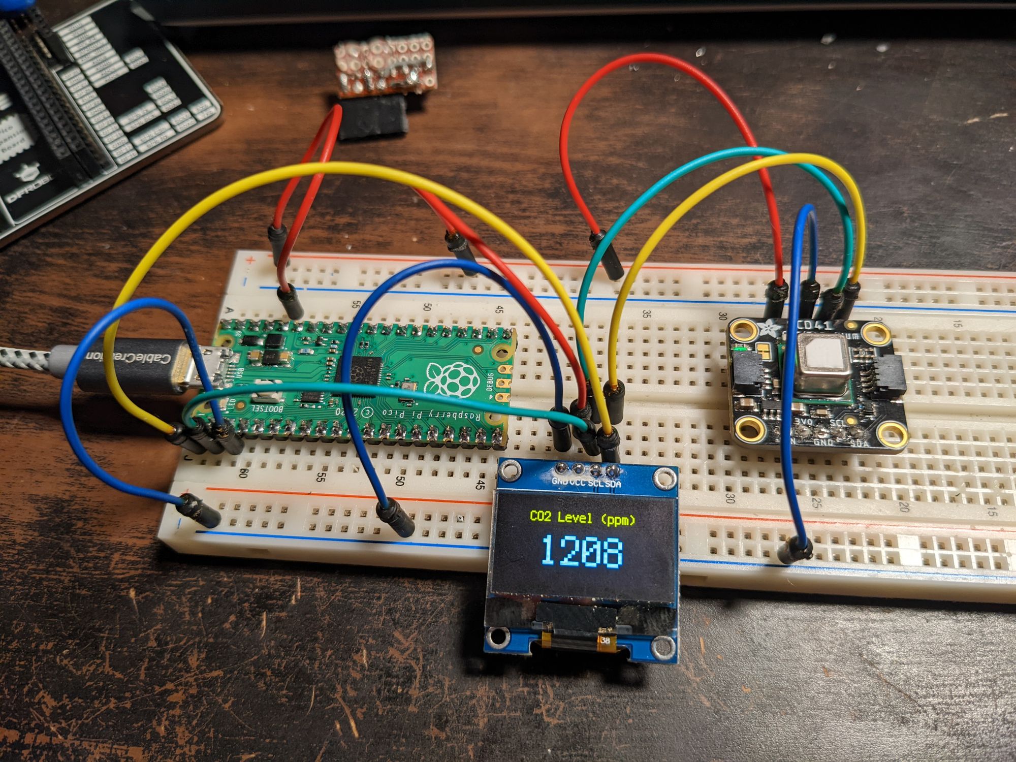
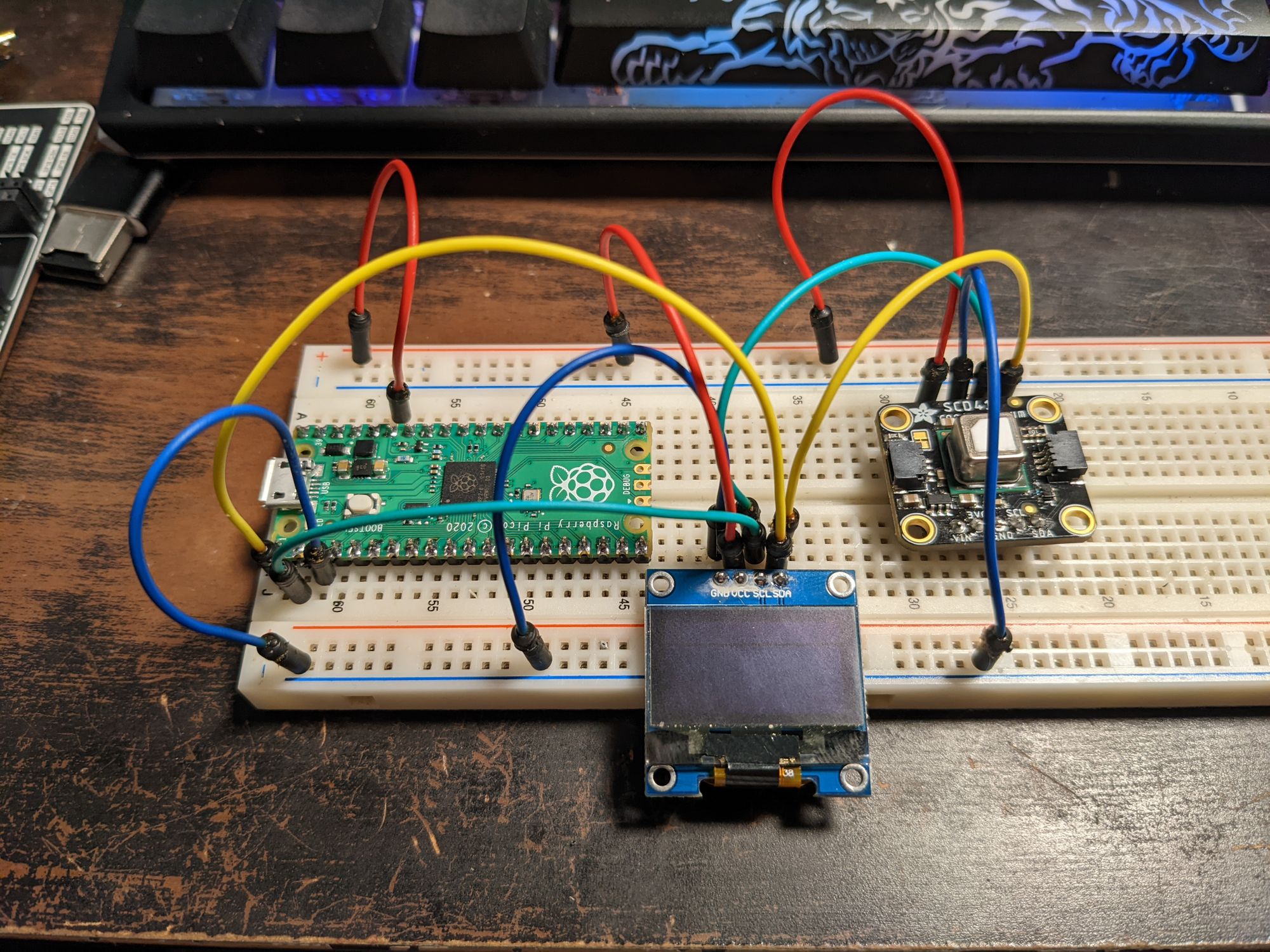
The final result should look more or less like this (again, ignoring that my sensor's pins look weird because it's on a riser):
The Code
Okay, hold up. Remember that library bundle we downloaded? Yeah, we need to get a couple things from that. Go to wherever you extracted it and open up the lib directory. You'll want to plug in the Pico (without holding BOOTSEL this time - just a normal boot) and open up the CIRCUITPY drive as well. Copy over the following libraries from the bundle's lib directory to the CIRCUITPY lib directory:
adafruit_display_text[whole directory - this is for displaying and formatting text]adafruit_displayio_ssd1306.mpy[single file - this is the driver for the display]adafruit_scd4x.mpy[single file - this is the driver for the co2 sensor]
Now open up your code.py file in the root of the CIRCUITPY drive and we can start programming.
Now copy/paste or type the following into your code.py file. I've commented the file (comments begin with #) so you can follow the logic even if you've never programmed before. Understanding what the code is doing will help you troubleshoot if things aren't working.
# Loading of libraries (builtin and from the /lib directory)
import time # used to sleep our program for 5 seconds
import board # maps the Pico's pins to python objects
import busio # lets us set up a way to talk to our devices
import displayio # lets us do graphical things on the display
import terminalio # needed for the font
import adafruit_scd4x
from adafruit_displayio_ssd1306 import SSD1306
from adafruit_display_text import label
# Reset the I/O before we initialize new display drivers
displayio.release_displays()
# Configure the bus
i2c = busio.I2C(scl=board.GP1, sda=board.GP0, frequency=400000)
# Set up display
i2c_display = displayio.I2CDisplay(i2c, device_address=0x3c)
display = SSD1306(i2c_display, width=128, height=64)
# I like to be in control of when the screen refreshes:
display.auto_refresh = False
# Create a display group to hold our labels
group = displayio.Group()
# Label for the description
header = label.Label(font=terminalio.FONT, text="CO2 Level (ppm)", color=0xFFFFFF)
header.anchor_point = (0.5, 0)
header.anchored_position = (64, 1)
# Label for the actual measurement, to be updated dynamically
level = label.Label(font=terminalio.FONT, scale=3, text="...", color=0xFFFFFF)
level.anchor_point = (0.5, 0.5)
level.anchored_position = (64, 32)
# Add the labels to the group, and tell the display to show the group.
group.append(header)
group.append(level)
display.show(group)
# Initialize sensor and start measuring periodically (~5 seconds)
co2 = adafruit_scd4x.SCD4X(i2c)
co2.altitude = 1045
co2.start_periodic_measurement()
# Retrieve sensor readings on a loop
while True:
# Check if sensor has new data and update the label if so
if co2.data_ready:
level.text = str(round(co2.CO2 if co2.CO2 else 0.0))
display.show(group)
# Refresh the display and wait 5 seconds
display.refresh()
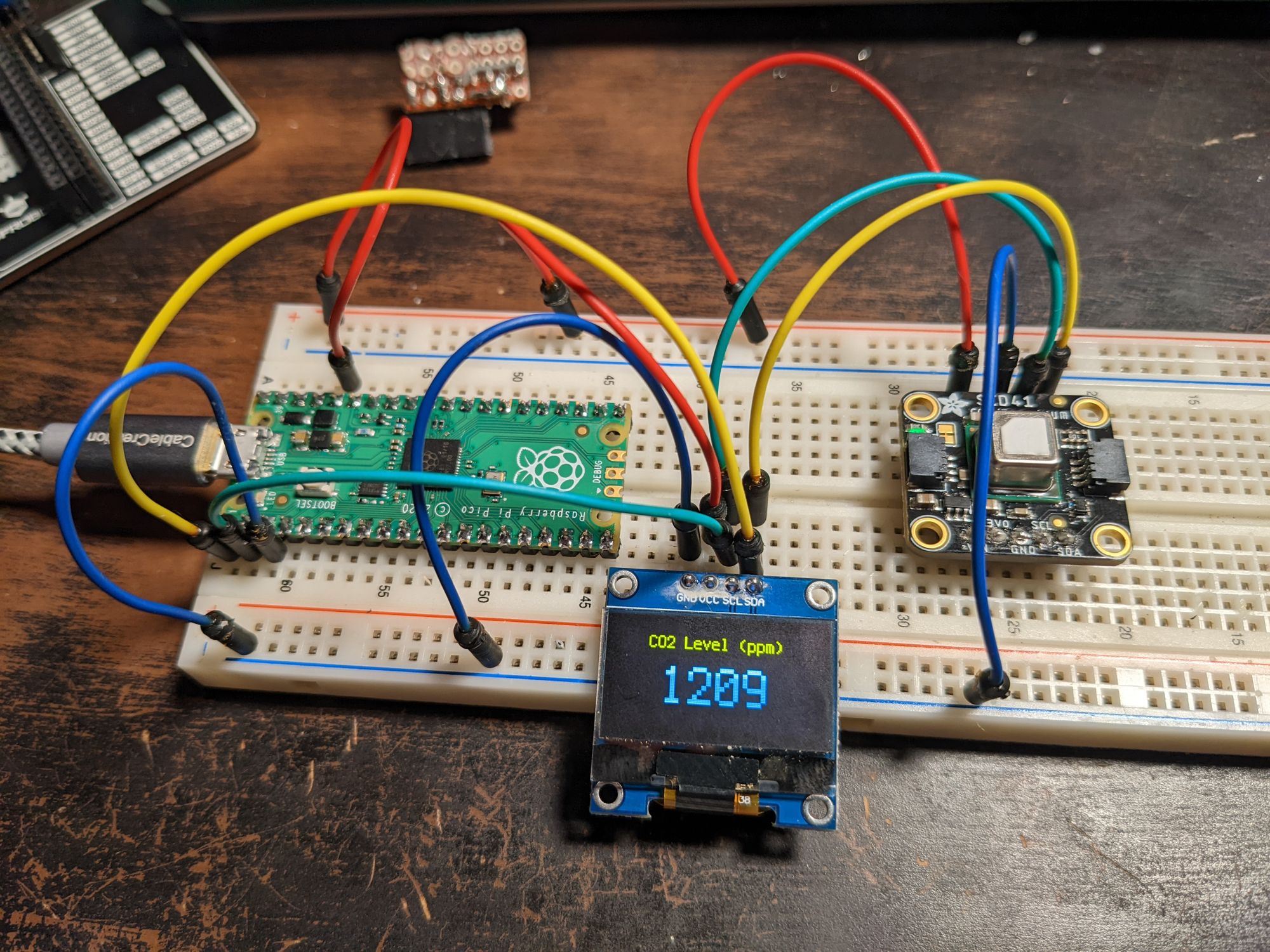
time.sleep(5)Adjust the line that says co2.altitude = 1045 so that it reflects the average altitude in your area. Save your code.py file and the circuit should start working! You'll see "..." on the display until the sensor is ready to give a CO2 readout. It'll look something like this (hopefully with lower CO2 levels than mine):
The sensor is capable of measuring temperature and humidity as well, but that's out of scope of this write-up.
If your circuit isn't working on the first try, don't worry. Even if you soldered your connections, you can always clip the wires or desolder (try not to overheat your components though!). Unplug the Pico and go over the wiring instructions again. You'll get it!
And congratulations, you have a (little bit janky, but inexpensive) portable CO2 sensor! I don't have any extra perfboard or I'd demonstrate what it looks like properly wired up. If your wires are loose, you can try mounting your creation into a small tin or project box (silicone works well to glue the parts into place), making sure there is a large enough opening for your sensor to properly read the CO2 levels in the air.
BONUS GUIDE
Even easier solutions in this section, but somewhat less available and/or more expensive parts. Your mileage may vary.
Wiring and coding the Badger2040 in CircuitPython
The Pimoroni Badger2040 is built to be used as a conference badge but it can do so much more. It features a Raspberry Pi 2040 (same microprocessor as in the Pi Pico) and a builtin e-ink display. It costs about $25 CAD for the unit itself, and around $35 for the kit. I don't really advise getting the kit unless you can't find it standalone - the neck strap is not adjustable and the battery pack is too weak to run the Badger and a sensor.
Some advantages of using the Badger instead of the method I detailed above are:
- No soldering if you don't want to - The Badger features a "QWIIC" (aka: "STEMMA/QT") connector which lets you connect I2C devices such as sensors without needing to solder. You'll need at least one QWIIC/STEMMA/QT cable, and your sensor must also have hookups for it (the Adafruit SCD40/41 has two!).
- Wiring literally involves plugging in a cable. That's it.
- It uses the increasingly more common USB-C connector.
- It has a JST battery connector. You can use a rechargeable battery with it (also without soldering) but the Badger has no charge circuit so you'll need a separate charger.
- It's going to be a little more presentable than a fully DIY solution if you need your device to look pro.
- The screen is e-ink which means it's sharp, viewable in any light, and low/no power when not updating. Very different from the OLED I used above.
- Mappable buttons! This means ability to switch between displays, change configuration, etc.!
Some disadvantages:
- Could be more costly depending where in the world you are, and what parts you already have available.
- The Badger 2040 has far more limited production than the Raspberry Pi Pico. This means it'll be more difficult to get.
Okay, enough said, here's the CircuitPython download link for the Badger 2040 (it comes with MicroPython, but I prefer CircuitPython in this case). The instructions here are pretty much the same as in the Setting up your Raspberry Pi Pico section above, but substitute the Badger 2040 firmware, a USB-C cable, and holding down the "boot/usr" button while powering up.
Once installed, you'll see the CIRCUITPY drive. Copy the following libraries from the Library bundle downloaded in the previous instructions into the lib directory within CIRCUITPY:
adafruit_display_text(whole directory)adafruit_scd4x.mpy(single file)
Now here comes the wiring guide:
- Connect QWIIC/STEMMA/QT cable to Badger 2040.
- Connect other end of QWIIC/STEMMA/QT cable to your sensor.
... that's it! It feels too easy, but rest assured it'll work. The back of your Badger should now look something like this:
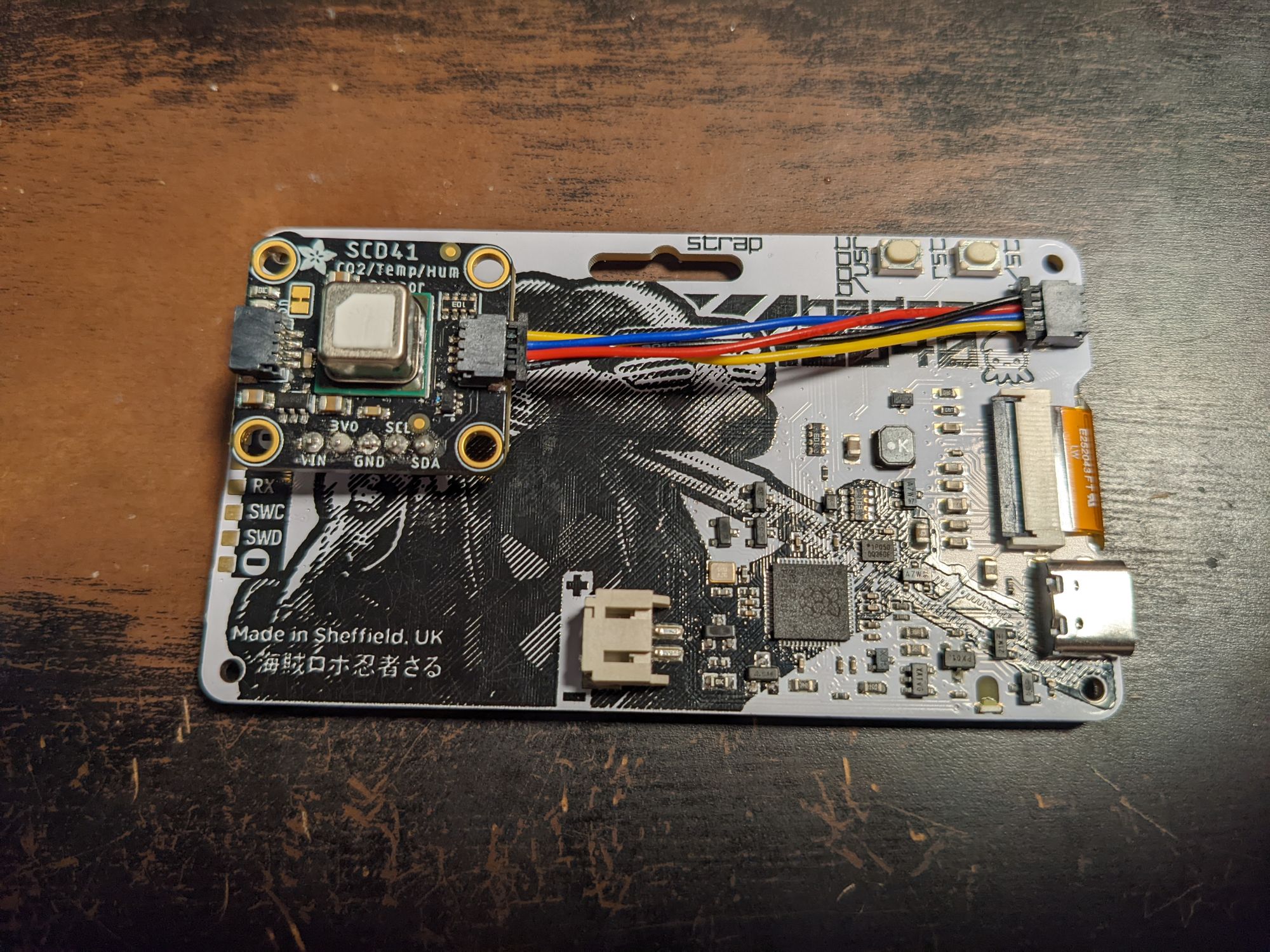
You can stick the sensor onto the back with some velcro or double-sided tape if you like. Just remember the sensor needs room to breathe so you'll want to hold the badger up in the air when trying to get a good measurement.
And now for the code, which will be very similar to the code we used above:
# Loading of libraries (builtin and from the /lib directory)
import time # used, in this case, to sleep our program
import board # maps the Pico's pins to python objects
import displayio # lets us do graphical things on the display
import vectorio
import terminalio # needed for the font
import supervisor # stops autoreload which is too quick for e-ink:
supervisor.disable_autoreload()
import adafruit_scd4x
from adafruit_display_text import label
# Set up display
display = board.DISPLAY
# Create a display group to hold our labels
group = displayio.Group()
# Set background to a light colour
palette = displayio.Palette(1)
palette[0] = 0xFFFFFF
rectangle = vectorio.Rectangle(pixel_shader=palette, width=display.width + 1, height=display.height, x=0, y=0)
# Label for the description
header = label.Label(font=terminalio.FONT, scale=2, text="CO2 Level (ppm)", color=0)
header.anchor_point = (0.5, 0)
header.anchored_position = (round(display.width / 2), 1)
# Label for the actual measurement, to be updated dynamically
level = label.Label(font=terminalio.FONT, scale=5, text="...", color=0)
level.anchor_point = (0.5, 0.5)
level.anchored_position = (round(display.width / 2), round(display.height / 2))
# Add the labels to the group, and tell the display to show the group.
group.append(rectangle)
group.append(header)
group.append(level)
display.show(group)
# Wait a short time to prevent refreshing too quickly.
display.refresh()
# # Initialize sensor and start measuring periodically
co2 = adafruit_scd4x.SCD4X(board.I2C())
co2.altitude = 1045
# Use low power mode at ~30 seconds
co2.start_low_periodic_measurement()
# Sleep a few seconds to wait for initial value
time.sleep(5)
# Retrieve sensor readings on a loop
while True:
# Check if sensor has new data and update the label if so
if co2.data_ready:
level.text = str(round(co2.CO2 if co2.CO2 else 0.0))
# Refreshes are more intensive on e-ink.
# This time we'll only refresh when data is ready.
# Wait a short time to prevent refreshing too quickly
display.refresh()
# Refresh the display and wait 30 seconds until the next update
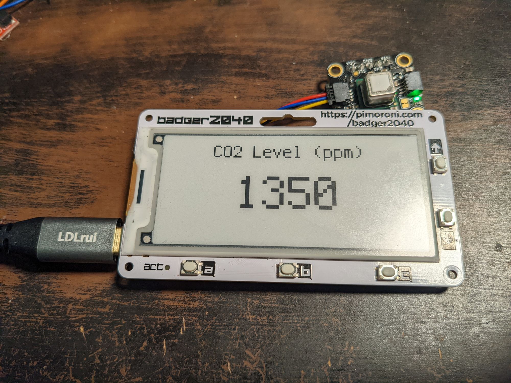
time.sleep(30)Again, update the number in co2.altitude = 1045 to reflect your approximate altitude before saving.
You should see results something like the following:
This code is just a touch more complex than the previous code. With e-ink, which has a slow refresh time, we need to make sure it doesn't update too rapidly or we risk the program crashing. If you get an error about too quick a refresh while working on the badger, eject its drive, unplug it, and plug it back in.
For portability, you can use a ~3.7v battery pack with a JST connector, or you can just use a USB power brick. Either is perfectly fine.