Preparation
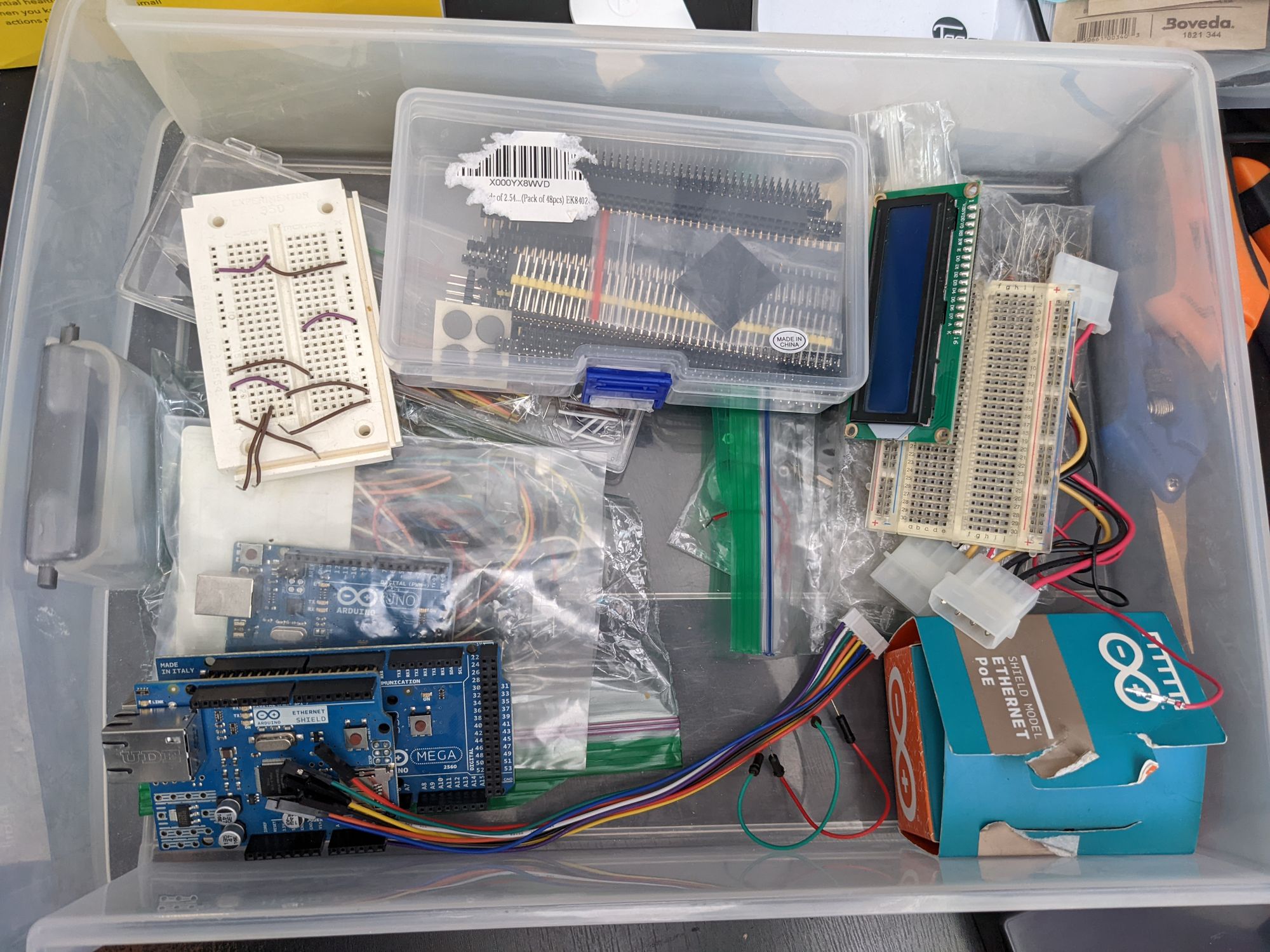
Earlier this week, my shipment of ESP32 boards arrived and I quickly got to work. I rounded up all the old components (an easier task than expected as my partner had sorted them for use in her Raspberry Pi explorations some time ago) and cracked open the box from Sparkfun.
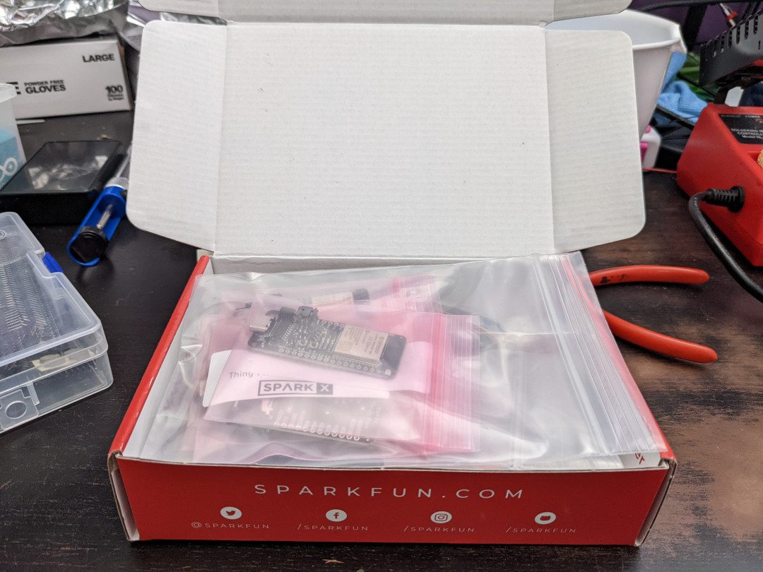
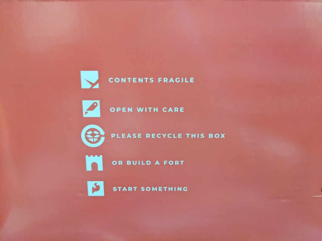
I really appreciate their messaging on the bottom of the box in particular:
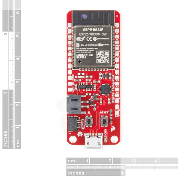
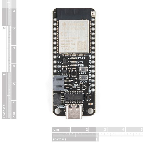
I had originally ordered an ESP32-C3-WROOM-02 development board as well as a number of Thing Plus C boards before realizing the C3 is not yet supported by ESPHome. Being a newb and being unsure if the Thing Plus C would be compatible with the ESP32-C3 or the original ESP32, I decided to also order some original Thing Plus ESP WROOM boards from Mouser (the boards were backordered on Sparkfun). Fortunately both sets of boards arrived at the same time, and it turns out both varieties are compatible with the original ESP32, making them usable in ESPHome for Home Assistant.
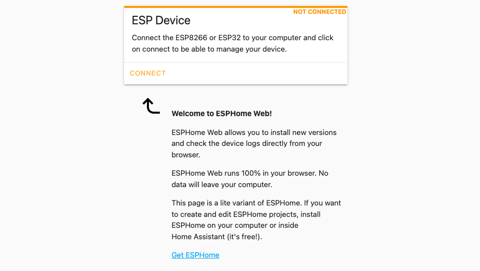
I had already installed ESPHome within Home Assistant some days prior, so I started by attaching a fresh new Thing Plus board to my Windows desktop via a MicroUSB cable, installing the CP210x USB-to-serial drivers, cracking open Chrome as my beloved Firefox browser doesn't support WebSerial, and going to https://web.esphome.io/ to prepare my device for "Adoption" by the ESPHome server. I'd use Chrome with my full ESPHome instance except that I also don't have a certificate set up yet on my internal Home Assistant instance, which is required to be able to flash over USB/serial with ESPHome.
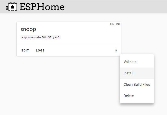
Once prepared for Adoption, which involved providing credentials for my wifi network, the device made itself known to ESPHome with a generic name affixed with 6 digits of what I assume to be the wireless hardware address. After filling out my wireless credentials in ESPHome's secrets.yaml file, I adjusted the naming, which involved a quick set of YAML edits and telling the device to build and install the changes wirelessly. I'm not showing the log results as they're jam-packed with my network information, but the wireless over-the-air update functionality is very impressive.
First Kick at the Can
Before trying to get a bunch of new things, I wanted to see if my old temperature and humidity sensors still worked. While they're much cheaper components these days, I paid quite a bit for them back in the day and it'd be a shame not to find a use for them. Unfortunately, they're not directly supported in ESPHome (I'm not shocked given their age). However, ESPHome is compatible with Arduino libraries so getting these to work would be a chance to learn more about custom sensor configuration in ESPHome and Home Assistant.
The Sensirion SHT21 was a chip I remember having some difficulty with back when I had it working on Arduino. Its main problem was having a static I2C address so multiple of the same device couldn't exist on the same I2C bus without some clever toggling circuitry. This is less of a problem with the ESP32 given it has two I2C buses, so I ignored that particular problem for now. What I wanted to accomplish here was just getting them working and reporting data to Home Assistant.
ESPHome's YAML configurations allow you to include libraries from the PlatformIO Registry so I scoured the registry for some SHT21 libraries and after some trial and error, I found a recently updated one that fit the bill: robtillaart/SHT2x. Following Rob's basic example code and the ESPHome guide to custom sensor development, I came up with the following which would poll every minute for both temperature and humidity:
#include "esphome.h"
#include <Wire.h>
#include <SHT2x.h>

class SHT21TempSensor : public PollingComponent, public Sensor {
 public:
  Sensor *temperature_sensor = new Sensor();
  Sensor *humidity_sensor = new Sensor();

  // constructor
  SHT21TempSensor() : PollingComponent(60000) {}

  uint32_t start;
  uint32_t stop;

  SHT2x sht;

  float get_setup_priority() const override {
  	return esphome::setup_priority::AFTER_CONNECTION;
  }

  void setup() override {
    // This will be called by App.setup()
    sht.begin();
  }

  void update() override {
    start = micros();
    sht.read();
    stop = micros();

    float temperature = sht.getTemperature();
    temperature_sensor->publish_state(temperature);

    float humidity = sht.getHumidity();
    humidity_sensor->publish_state(humidity);
  }
};For this to work, I had to include these libraries at the top of Snoop's YAML configuration, and add a custom sensor block to instantiate and poll a sensor object based on my class:
esphome:
  name: snoop
  libraries:
    - Wire
    - robtillaart/SHT2x
  includes:
- sht21_sensor.h# Enable the I2C bus and set the pins to those used by the Qwiic port
i2c:
sda: 23
scl: 22
scan: true
id: i2c_bus_a
# Define a custom sensor with lambda for fetching values
sensor:
- platform: custom
lambda: |-
auto my_sensor = new SHT21TempSensor();
App.register_component(my_sensor);
return {my_sensor->temperature_sensor, my_sensor->humidity_sensor};
sensors:
- name: "Grow Tent Temperature"
accuracy_decimals: 1
unit_of_measurement: "°C"
state_class: measurement
- name: "Grow Tent RH"
accuracy_decimals: 1
unit_of_measurement: "%"
state_class: measurementI buillt and over-the-air installed the new firmware to Snoop. All that remained was to wire up the sensor to the ESP32 board, made much easier through the use of a Qwiic adapter, allowing me to simply connect a cable.
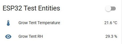
After adding an Entity list in Home Assistant's lovelace interface, I could now see the values updating once per minute. Success!
What Was This All For Again?
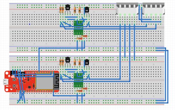
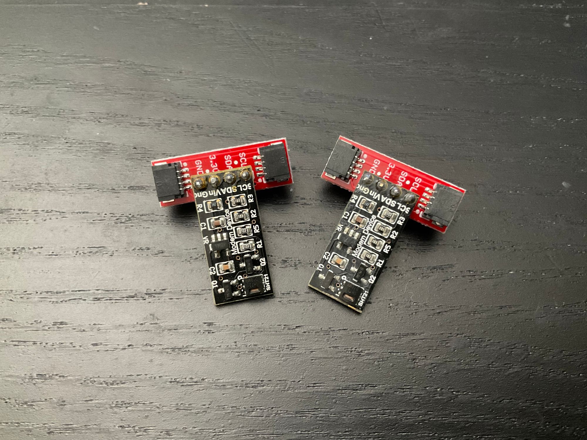
While temperature and humidity sensors are a useful addition, the goal here was originally to make a PWM (Pulse Width Modulation) fan controller for the AC Infinity fans in my grow tent. I knew this was possible from a number of forum posts I stumbled across. The key element would be to confirm the pinout from the fans to the controllers, and to make use of opto-isolators to keep the 10V of the fan away from the 3.3V of my ESP32 controller.
The "code" part of the project was the easiest work yet, requiring only specification of the PWM pins and frequency.
Selection of the pins was a bit challenging as I needed to learn more about the ESP32 board - while almost all pins can perform PWM, several of the pins are considered off limits due to their association with the bootloader. Pins 5 and 18 on my board are next to each other and free from worries of that nature.
I had already soldered pins to Snoop and my opto-isolator boards so I soldered receptacles for them onto a piece of perfboard I still had lying around. The manufacturer-supplied fan controller connects via a connector like those on old ATA hard drives and power supplies so I made use of a Molex adapter that came with one of my old video cards to connect the fans to the board. Rather than use the SHT21 as a temperature/sensor in the end, I connected one of the dual chip environmental sensor boards I just received.
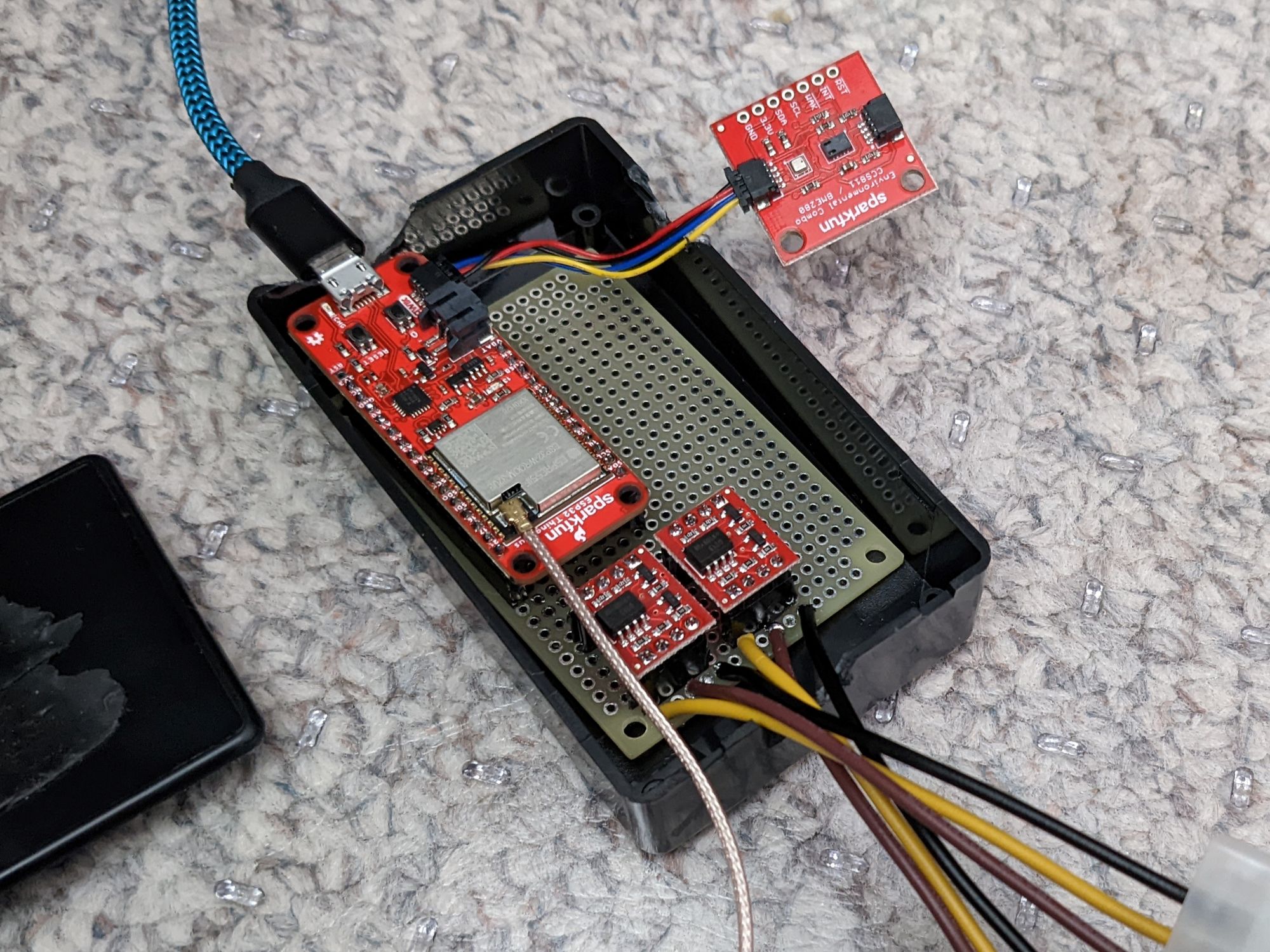
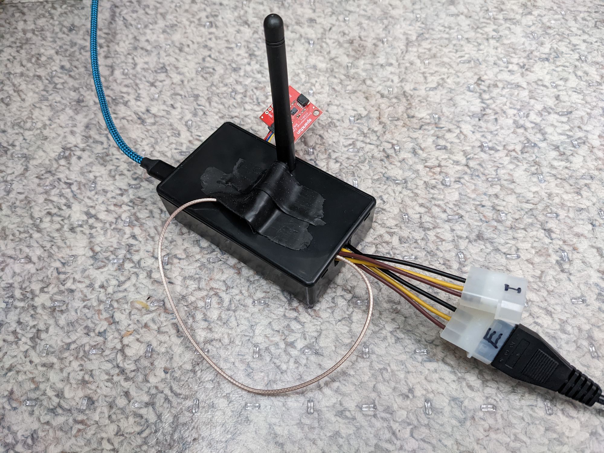
I quickly added the configuration for my environmental sensor board to Snoop's YAML file and removed references to the SHT21 for now (they'll likely get used on other projects with a little more robust code).
The end of my YAML config now looked more-or-less like the following:
sensor:
# Combined Sparkfun Board - both chips are supported in ESPHome
- platform: ccs811
eco2:
name: "Snoop Tent eCO2"
tvoc:
name: "Snoop Tent TVOC"
address: 0x5B
update_interval: 60s
- platform: bme280
temperature:
name: "Snoop Tent Temperature"
oversampling: 16x
pressure:
name: "Snoop Tent Pressure"
unit_of_measurement: kPa
accuracy_decimals: 3
# Adjust measurement to kPa as it defaults to hPa
filters:
- lambda: |-
return x / 10.0;
humidity:
name: "Snoop Tent Humidity"
address: 0x77
update_interval: 60s
# PWM pinouts for fan optoisolator circuits
output:
- platform: ledc
pin: GPIO5
# Fans use 5000 Hz from factory; 4882 Hz is recommended for clean divides
frequency: "4882Hz"
id: exhaust_fan_pwm
- platform: ledc
pin: GPIO18
# Fans use 5000 Hz from factory; 4882 Hz is recommended for clean divides
frequency: "4882Hz"
id: intake_fan_pwm
fan:
- platform: speed
name: "Grow Tent Exhaust Fan"
# Original controller has 8 speeds (and off)
speed_count: 8
output: exhaust_fan_pwm
# Ensure fans are brought online if previous speed setting is forgotten
restore_mode: RESTORE_DEFAULT_ON
- platform: speed
name: "Grow Tent Intake Fan"
# Original controller has 8 speeds (and off)
speed_count: 8
output: intake_fan_pwm
# Ensure fans are brought online if previous speed setting is forgotten
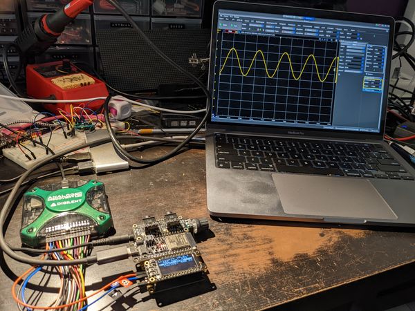
restore_mode: RESTORE_DEFAULT_ONI built and installed the new firmware to Snoop and spent a few hours testing and troubleshooting before it was ready to go. When testing the PWM controller, I experienced a bit of flakiness which ended up being a poor solder joint. This is a good reminder to check your solder joints are clean and bonded to both the wire and the board.
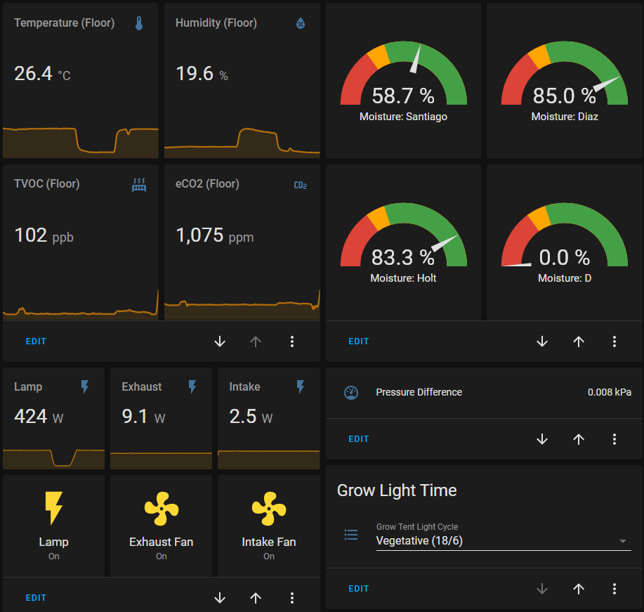
In the end, everything worked reliably. The fans being attached to wattage-measuring outlets allows me to remotely see the effects of changes to the fan speeds. Below is my current Grow Tent information panel (ignore the high eCO2 values for the moment - the chip is still calibrating).
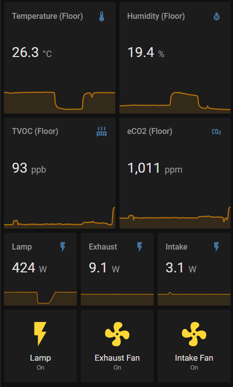
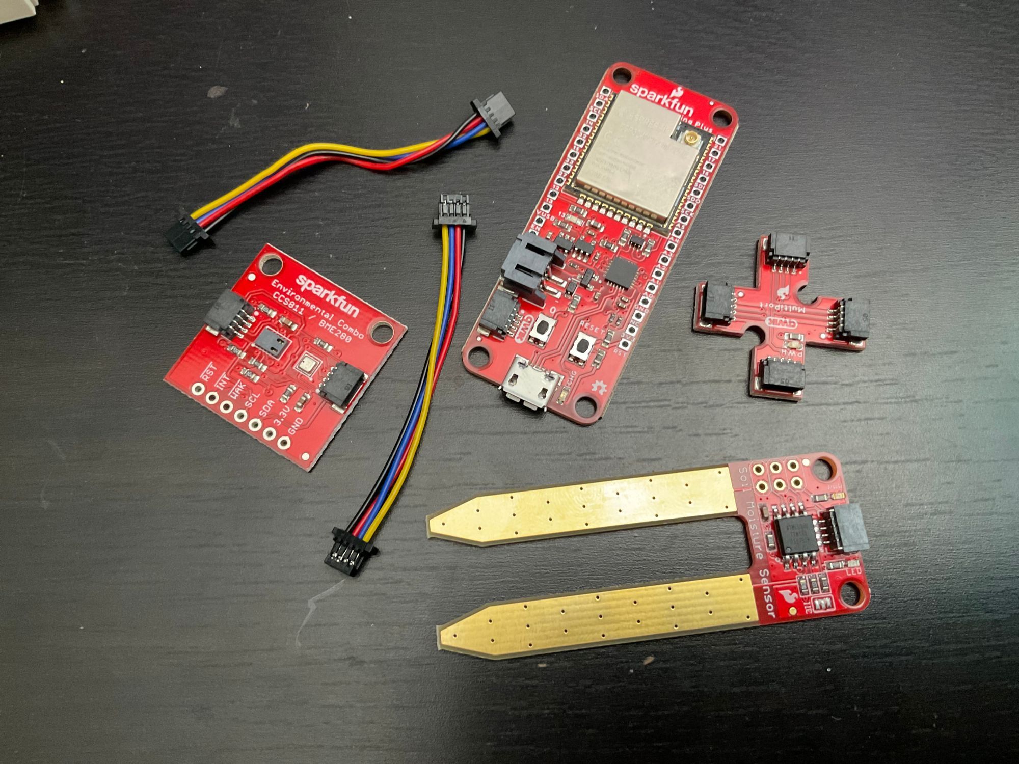
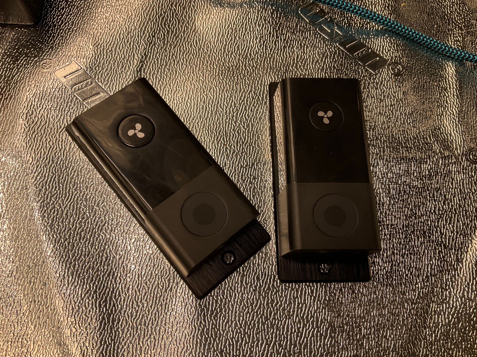
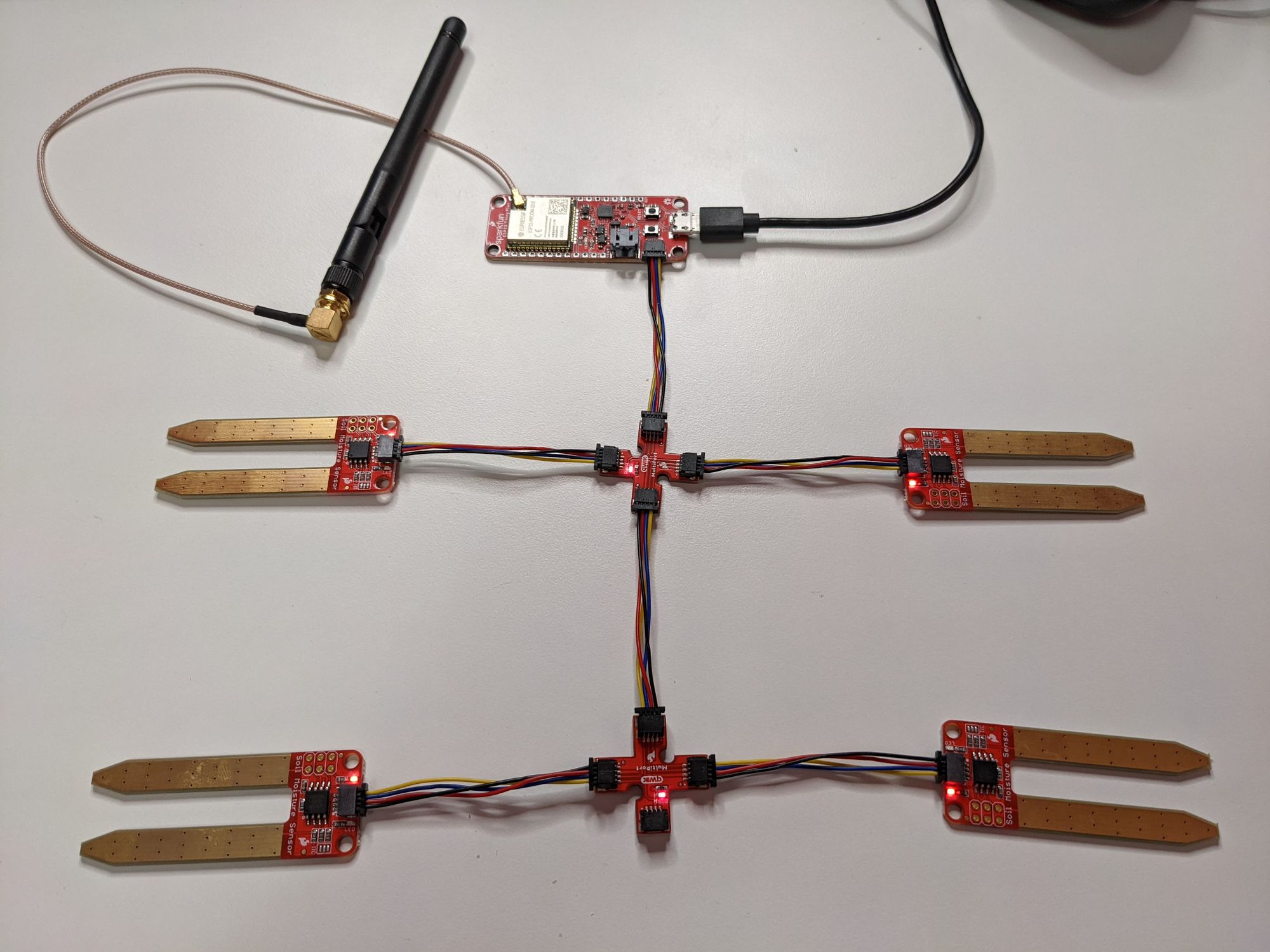
"But wait," you say, "wasn't there another kind of sensor in the photo at the very top?"
Yes, indeed. That's a moisture sensor and the last piece of the puzzle.
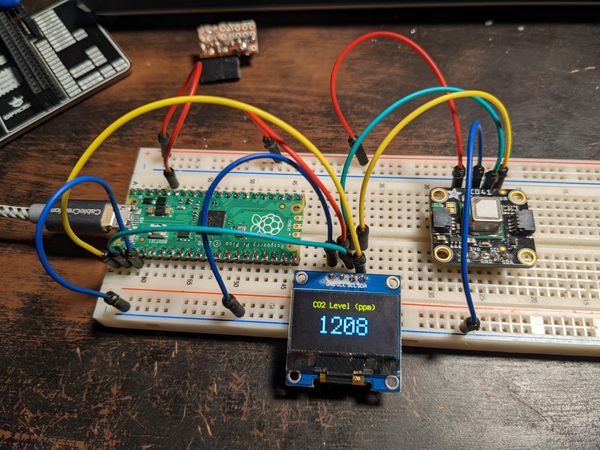
Bonus Round: Moisture Sensors
I bought four I2C Soil Moisture sensors and some longer Qwiic cables for this purpose. I originally wasn't sure if one ESP32 would be able to handle it all, but now I know better; the ESP32 is a powerful little microcontroller. Even so, now that Snoop was on full-time duty, I had to spin up a second ESP32 to configure and test the sensors.
Unfortunately, these moisture sensors are not directly supported by ESPHome so I leaned on some of Sparkfun's examples scattered throughout the internet and cobbled together a custom sensor library for them that reads up to four devices. It polls only every 5 minutes, both to preserve the sensor and because there really isn't an interesting amount of change within 5 minutes. I'll probably update it to 10 or even 30 minutes in future.
#include "esphome.h"
#include <Wire.h>
#define LOG_PREFIX "SFMoistureSensor"
#define SFMS_COMMAND_LED_OFF        0x00
#define SFMS_COMMAND_LED_ON         0x01
#define SFMS_COMMAND_CHANGE_ADDRESS 0x03
#define SFMS_COMMAND_GET_VALUE      0x05
#define SFMS_COMMAND_NOTHING_NEW    0x99
#define SFMS_ADDRESS_A              0x28
#define SFMS_ADDRESS_B              0x29
#define SFMS_ADDRESS_C              0x2A
#define SFMS_ADDRESS_D              0x2B
#define LOW_CALIBRATION_CUTOFF      750
#define HIGH_CALIBRATION_CUTOFF     990

class SFMoistureSensor : public PollingComponent, public Sensor {
 public:
  Sensor *sensor_a = new Sensor();
  Sensor *sensor_b = new Sensor();
  Sensor *sensor_c = new Sensor();
  Sensor *sensor_d = new Sensor();

  SFMoistureSensor() : PollingComponent(300000) {}

  float get_setup_priority() const override {
  	return esphome::setup_priority::AFTER_CONNECTION;
  }

  void setup() override {
    ESP_LOGD(LOG_PREFIX, "Instantiating");

    Wire.begin();
  }

  void update() override {
    sensor_a->publish_state(get_value(SFMS_ADDRESS_A));
    sensor_b->publish_state(get_value(SFMS_ADDRESS_B));
    sensor_c->publish_state(get_value(SFMS_ADDRESS_C));
    sensor_d->publish_state(get_value(SFMS_ADDRESS_D));
  }

  // LED is off, and a -1 if an error occurred.
  float get_value(uint8_t address) {
    ledOn(address);
    Wire.beginTransmission(address);
    Wire.write(SFMS_COMMAND_GET_VALUE);
    Wire.endTransmission();
    uint16_t value = 1023;
    int16_t c_value = value;
    float f_value = 0.0;

    Wire.requestFrom((uint8_t) address, (uint8_t) 2);

    while (Wire.available()) {
      uint8_t value_l = Wire.read();
      uint8_t value_h = Wire.read();
      value=value_h;
      value<<=8;
      value|=value_l;
      }
    ledOff(address);

    // Preserve raw value
    value = abs(value - 1023);

    // Calibrate within defined range
    c_value = value > HIGH_CALIBRATION_CUTOFF ? HIGH_CALIBRATION_CUTOFF : value;
    c_value = c_value - LOW_CALIBRATION_CUTOFF;
    c_value = c_value < 0 ? 0 : c_value;

    // Generate percentage value from 0 (dry) to 100 (wet)
    f_value = ((float) c_value / (HIGH_CALIBRATION_CUTOFF - LOW_CALIBRATION_CUTOFF)) * 100.0;

    ESP_LOGD(LOG_PREFIX, "Device: 0x%02x; Raw Value: %i, Final Value: %f ", address, value, f_value);
    return f_value;
  }

  // boolean changeAddress(uint8_t old_address, uint8_t new_address) {
  //   Wire.beginTransmission(old_address);
  //   if (Wire.endTransmission() != 0) {
  //     ESP_LOGD(LOG_PREFIX, "Check Connections. No device found.");
  //     return (false);
  //   }

  //   if (new_address < 0x07 || new_address > 0x78) {
  //     ESP_LOGD(LOG_PREFIX, "Invalid new I2C address");
  //     return (false);
  //   }

  //   Wire.beginTransmission(old_address);
  //   Wire.write(SFMS_COMMAND_CHANGE_ADDRESS);
  //   Wire.write(new_address);
  //   Wire.endTransmission();
  //   return (true);
  // }

  void ledOn(uint8_t address) {
    Wire.beginTransmission(address);
    Wire.write(SFMS_COMMAND_LED_ON);
    Wire.endTransmission();
  }

  void ledOff(uint8_t address) {
    Wire.beginTransmission(address);
    Wire.write(SFMS_COMMAND_LED_OFF);
    Wire.endTransmission();
  }
};You'll notice a commented-out block for the changeAddress function. This was essential for preparing these devices for use. The I2C controller on each sensor defaults to 0x28 as its address but can be changed to any value between 0x07 and 0x78. In order to use multiple sensors the way I had planned they each had to be adjusted to a different address and I needed to use the ESP32 to change each one. This would probably have been more easily done if I had been using a Raspberry Pi as my workstation and used its own I2C support to set each sensor's address. Mea culpa.
In any case, all four of my moisture sensors now had unique addresses from 0x28 through 0x2B. The raw value received is a number in the range of 0 through 1023 where 1023 is the dryest. This wouldn't do for my purposes. First, the scale would need to be reversed so higher is wetter. Second, because the units are nonsensical a percentage value seemed more appropriate. Third, I needed a way to "calibrate", selecting a numeric range that's appropriate to soil (even "dry" soil has some conductivity). The above code is what I've settled on for now.
I added sf_moisture_sensor.h to the includes at the top of my YAML config and in the sensor block, I added the following:
# Custom library for moisture sensing
# - depends on sf_moisture_sensor.h, included above.
- platform: custom
lambda: |-
auto my_sensor = new SFMoistureSensor();
App.register_component(my_sensor);
return {my_sensor->sensor_a, my_sensor->sensor_b, my_sensor->sensor_c, my_sensor->sensor_d};
sensors:
- name: "Snoop Soil Moisture A"
accuracy_decimals: 1
unit_of_measurement: "%"
icon: "mdi:water-percent"
state_class: measurement
- name: "Snoop Soil Moisture B"
accuracy_decimals: 1
unit_of_measurement: "%"
icon: "mdi:water-percent"
state_class: measurement
- name: "Snoop Soil Moisture C"
accuracy_decimals: 1
unit_of_measurement: "%"
icon: "mdi:water-percent"
state_class: measurement
- name: "Snoop Soil Moisture D"
accuracy_decimals: 1
unit_of_measurement: "%"
icon: "mdi:water-percent"
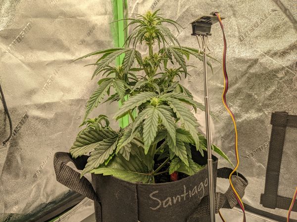
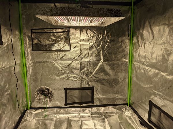
state_class: measurementOnce more, I built and installed the code to Snoop, then went into the tent to install three of the sensors (I only have 3 plants at the moment). The 4th sensor just reports a 0 value until connected and placed in soil.
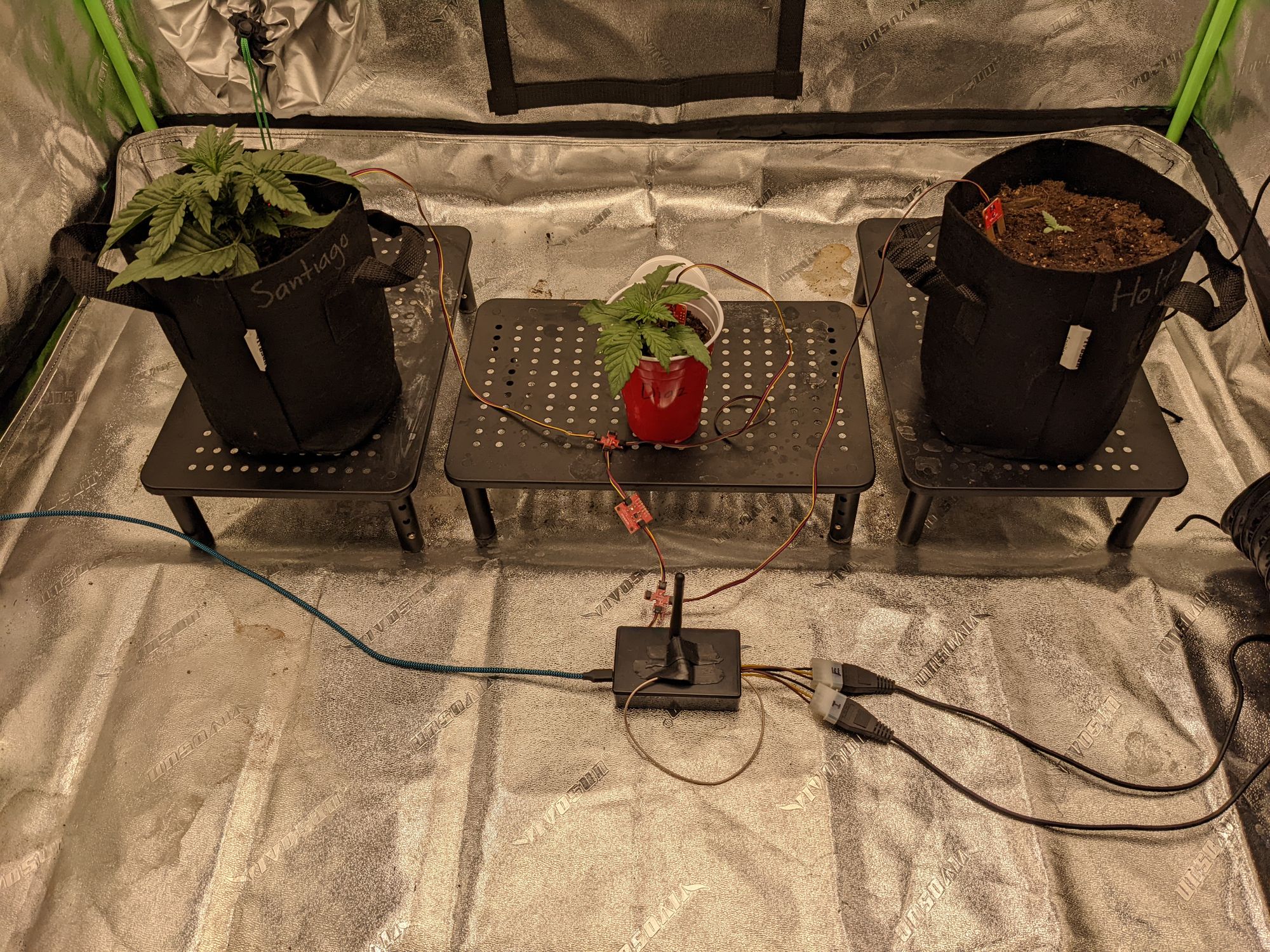
Because these are cannabis plants and at least one of them is photoperiod, I took a tiny screwdriver and scratched off the solder to the always-on power LEDs on each board, making sure that night time stays dark for the plants.